1-8. Circuit configuration of a series regulator
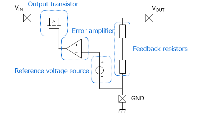
Basically, a series regulator consists of the following four blocks:
Output transistor
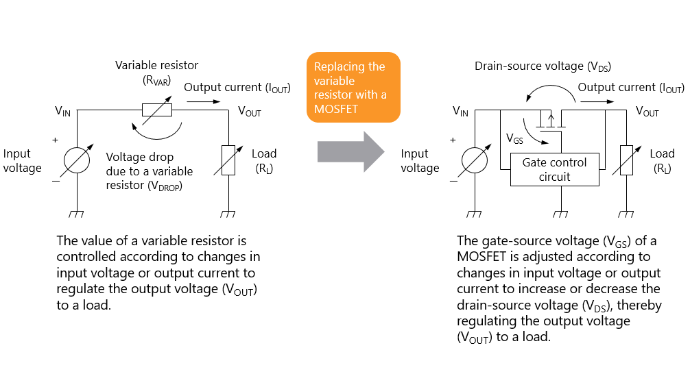
The output transistor is placed in series between the input and output pins of a series regulator. In response to changes in input voltage or output current, its gate voltage or base current is controlled by a signal from an error amplifier. As a result, the output transistor acts as a variable resistor to maintain output voltage regulation.
Reference voltage source
This is a reference voltage source for the error amplifier. The error amplifier controls the gate or base of the output transistor according to this reference voltage to maintain output voltage regulation.
Feedback resistors
The feedback resistors divide the output voltage to generate a feedback voltage. The error amplifier compares the feedback voltage to the reference voltage to control the output voltage. Two feedback resistors are connected in series between the VOUT and GND pins. The midpoint voltage between these resistors is applied to the error amplifier.
Error amplifier
The error amplifier compares the feedback voltage (i.e., the midpoint voltage of the two feedback resistors) to the reference voltage. When the feedback voltage is lower than the reference voltage, the error amplifier increases the drive capability of the MOSFET to reduce its drain-source voltage and thereby increase the output voltage.
When the feedback voltage is higher than the reference voltage, the error amplifier decreases the drive capability of the MOSFET to increase the drain-source voltage and thereby reduce the output voltage.
Chapter1 Introduction to Low-Dropout (LDO) Regulators
Related information
- Products
Low-Dropout Regulators (LDO Regulators) - Applidcation Notes
Application Notes - FAQs
LDO Regulators - Parametric Search
LDO Regulators - Stock Check & Purchase
Stock Check & Purchase


